> ## Documentation Index
> Fetch the complete documentation index at: https://devzone.nayax.com/llms.txt
> Use this file to discover all available pages before exploring further.
# Connection Interfaces
> Connector pinout, USB 2.0, and UART TTL connection specifications for the UNO-mini.
The UNO-mini connects to the host controller through a single 8-pin Molex connector that multiplexes USB 2.0 and UART TTL interfaces.
## Connector
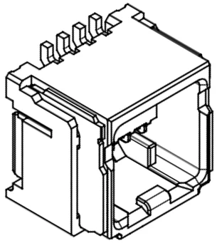
The Molex 5054330871 8-pin connector carries both the USB and UART interfaces. Only one communication interface should be active at a time.
 The following diagram shows the pin numbering as seen from the mating face of the connector.
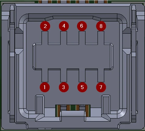 The following table lists all pin assignments.
| Pin | Signal |
| :-- | :--------------- |
| 1 | Host UART RX |
| 2 | Host UART TX |
| 3 | TEST LED |
| 4 | GND |
| 5 | GND\_EXT |
| 6 | USB-P |
| 7 | Vin Ext (5–12 V) |
| 8 | USB-N |
## SDK interface cable
Nayax can provide a reference SDK interface cable for integration and testing purposes.
The following table lists all pin assignments.
| Pin | Signal |
| :-- | :--------------- |
| 1 | Host UART RX |
| 2 | Host UART TX |
| 3 | TEST LED |
| 4 | GND |
| 5 | GND\_EXT |
| 6 | USB-P |
| 7 | Vin Ext (5–12 V) |
| 8 | USB-N |
## SDK interface cable
Nayax can provide a reference SDK interface cable for integration and testing purposes.
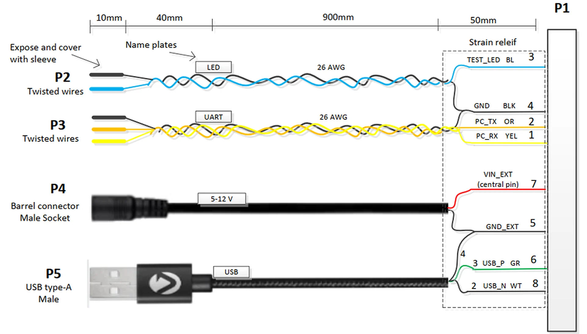 This reference cable is not included in the UNO-mini mass-production bill of materials.
## USB 2.0 connection
The UNO-mini supports USB 2.0 Full Speed (12 Mbps) communication with the host controller.
### Signal lines
Connect the USB interface using the following pin assignments:
* Connect USB D+ to pin 6 (USB-P).
* Connect USB D- to pin 8 (USB-N).
* Connect GND to both pin 4 and pin 5.
* Supply the full device power (up to 3 W peak) from the host via pin 7 (Vin Ext).
### Enumeration
Upon USB connection, the UNO-mini enumerates as a CDC (Communications Device Class) virtual serial port. The host OS assigns a COM port on Windows or a `/dev/ttyACMx` device node on Linux and Android.
* **Linux and Android**: No custom USB driver is required.
* **Windows**: The standard CDC driver (`usbser.sys`) is used. Install it manually if it is not loaded automatically.
### Cable requirements
Observe the following requirements when designing or selecting the USB cable:
* USB D+ and D- lines must be a twisted pair with impedance of 90 Ω ±15 Ω.
This reference cable is not included in the UNO-mini mass-production bill of materials.
## USB 2.0 connection
The UNO-mini supports USB 2.0 Full Speed (12 Mbps) communication with the host controller.
### Signal lines
Connect the USB interface using the following pin assignments:
* Connect USB D+ to pin 6 (USB-P).
* Connect USB D- to pin 8 (USB-N).
* Connect GND to both pin 4 and pin 5.
* Supply the full device power (up to 3 W peak) from the host via pin 7 (Vin Ext).
### Enumeration
Upon USB connection, the UNO-mini enumerates as a CDC (Communications Device Class) virtual serial port. The host OS assigns a COM port on Windows or a `/dev/ttyACMx` device node on Linux and Android.
* **Linux and Android**: No custom USB driver is required.
* **Windows**: The standard CDC driver (`usbser.sys`) is used. Install it manually if it is not loaded automatically.
### Cable requirements
Observe the following requirements when designing or selecting the USB cable:
* USB D+ and D- lines must be a twisted pair with impedance of 90 Ω ±15 Ω.
 * Maximum cable length: 3 m (per USB 2.0 specification for Full Speed devices).
* Use a shielded cable to minimize EMI. Connect the shield to chassis ground at the host end only (single-point grounding).
* Do not route the USB cable in the same conduit as high-current power wiring.
Hot-plugging the USB cable is not expected during normal operation. Ensure the host application handles USB disconnection and reconnection events gracefully and restores the communication session automatically.
## UART TTL connection
The UNO-mini supports UART TTL communication as an alternative to USB.
Do not connect the UNO-mini UART RX/TX lines directly to a 5 V logic system without a level-shifter. Doing so exceeds the absolute maximum input voltage and may permanently damage the UNO-mini. Use a bi-directional level-shifter such as the TXS0102 or SN74LVC2T45 if the host UART operates at 5 V.
### Signal lines
Connect the UART interface using the following pin assignments:
* Connect UART TX from the UNO-mini (host RX) to pin 1 (Host UART RX).
* Connect UART RX to the UNO-mini (host TX) to pin 2 (Host UART TX).
* Supply power (Vin) on pin 7, and connect GND to pins 4 and 5.
### UART parameters
The following table lists the UART interface parameters.
| Parameter | Value | Notes |
| :--------------------- | :------------------ | :--------------------------------------------------- |
| **Baud rate** | 115,200 bps | Default; configurable if required |
| **Data bits** | 8 | |
| **Stop bits** | 1 | |
| **Parity** | None | |
| **Flow control** | None | No hardware or software flow control |
| **Voltage level** | 3.3 V TTL | Do not connect 5 V logic directly |
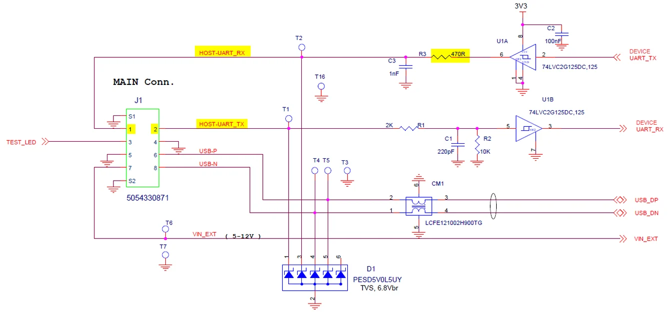
| **TX series resistor** | 470 Ω (on UNO-mini) | Host RX input resistance must be at least several kΩ |
### Host RX input impedance
The UNO-mini TX output line includes a 470 Ω series resistor as part of an RC filter. To avoid excessive voltage drop on the TX line, the host RX input impedance must meet the following requirements:
* Minimum: 5 kΩ
* Recommended: 10 kΩ to 100 kΩ (ensures less than 10% voltage drop across the 470 Ω series resistor)
* Maximum cable length: 3 m (per USB 2.0 specification for Full Speed devices).
* Use a shielded cable to minimize EMI. Connect the shield to chassis ground at the host end only (single-point grounding).
* Do not route the USB cable in the same conduit as high-current power wiring.
Hot-plugging the USB cable is not expected during normal operation. Ensure the host application handles USB disconnection and reconnection events gracefully and restores the communication session automatically.
## UART TTL connection
The UNO-mini supports UART TTL communication as an alternative to USB.
Do not connect the UNO-mini UART RX/TX lines directly to a 5 V logic system without a level-shifter. Doing so exceeds the absolute maximum input voltage and may permanently damage the UNO-mini. Use a bi-directional level-shifter such as the TXS0102 or SN74LVC2T45 if the host UART operates at 5 V.
### Signal lines
Connect the UART interface using the following pin assignments:
* Connect UART TX from the UNO-mini (host RX) to pin 1 (Host UART RX).
* Connect UART RX to the UNO-mini (host TX) to pin 2 (Host UART TX).
* Supply power (Vin) on pin 7, and connect GND to pins 4 and 5.
### UART parameters
The following table lists the UART interface parameters.
| Parameter | Value | Notes |
| :--------------------- | :------------------ | :--------------------------------------------------- |
| **Baud rate** | 115,200 bps | Default; configurable if required |
| **Data bits** | 8 | |
| **Stop bits** | 1 | |
| **Parity** | None | |
| **Flow control** | None | No hardware or software flow control |
| **Voltage level** | 3.3 V TTL | Do not connect 5 V logic directly |
| **TX series resistor** | 470 Ω (on UNO-mini) | Host RX input resistance must be at least several kΩ |
### Host RX input impedance
The UNO-mini TX output line includes a 470 Ω series resistor as part of an RC filter. To avoid excessive voltage drop on the TX line, the host RX input impedance must meet the following requirements:
* Minimum: 5 kΩ
* Recommended: 10 kΩ to 100 kΩ (ensures less than 10% voltage drop across the 470 Ω series resistor)
 ### Cable recommendations
Follow these guidelines when routing UART wiring:
* Maximum cable length: 1 m at 115,200 baud without additional line conditioning.
* Use shielded twisted pair for UART TX/RX lines. Reduce baud rate if communication errors occur.
* Keep UART wiring away from high-current power lines and switching power supplies to minimize noise coupling.
* In noisy environments, add ferrite beads at both ends of the UART lines.
## Next steps
Install the EMV Core SDK and begin your software integration.
Review the integration and certification milestones for your EMV Core project.
### Cable recommendations
Follow these guidelines when routing UART wiring:
* Maximum cable length: 1 m at 115,200 baud without additional line conditioning.
* Use shielded twisted pair for UART TX/RX lines. Reduce baud rate if communication errors occur.
* Keep UART wiring away from high-current power lines and switching power supplies to minimize noise coupling.
* In noisy environments, add ferrite beads at both ends of the UART lines.
## Next steps
Install the EMV Core SDK and begin your software integration.
Review the integration and certification milestones for your EMV Core project.