Connector
The Molex 5054330871 8-pin connector carries both the USB and UART interfaces. Only one communication interface should be active at a time.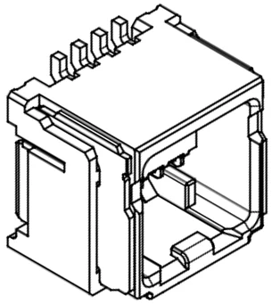
SDK interface cable
Nayax can provide a reference SDK interface cable for integration and testing purposes.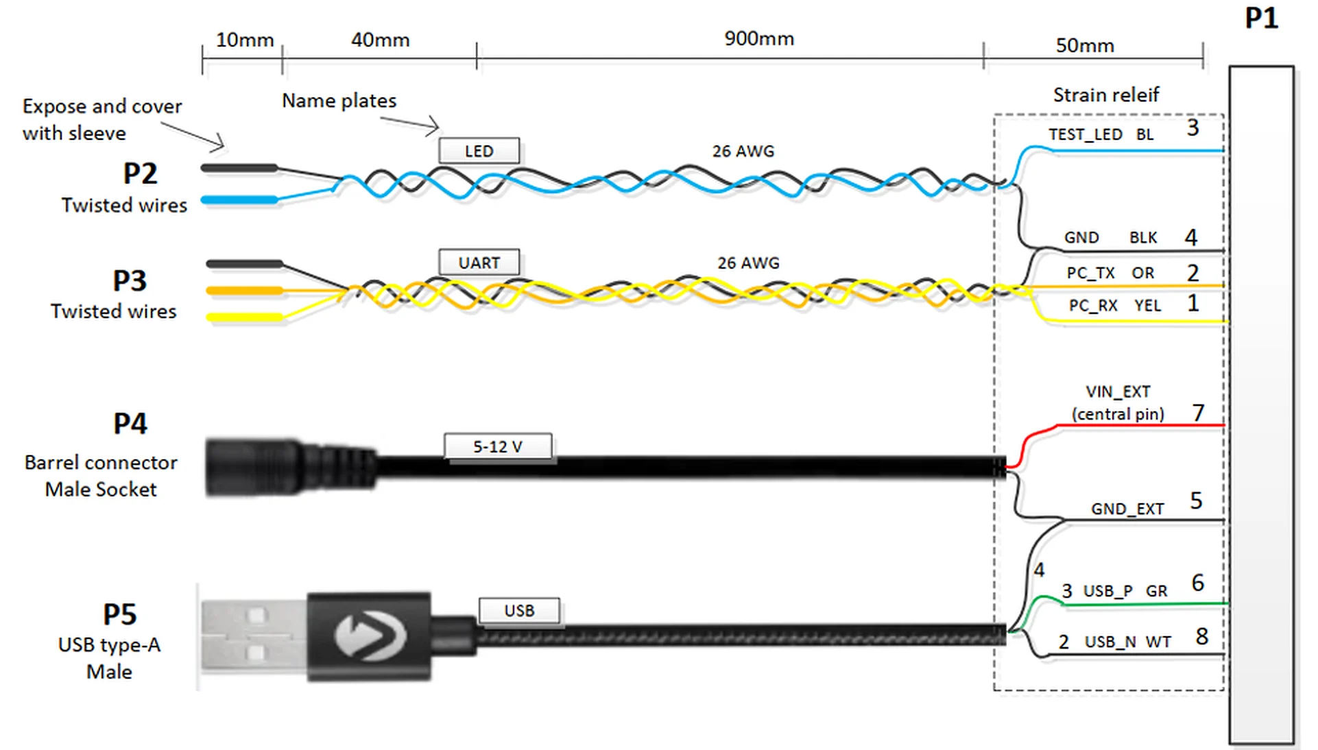
USB 2.0 connection
The UNO-mini supports USB 2.0 Full Speed (12 Mbps) communication with the host controller.Signal lines
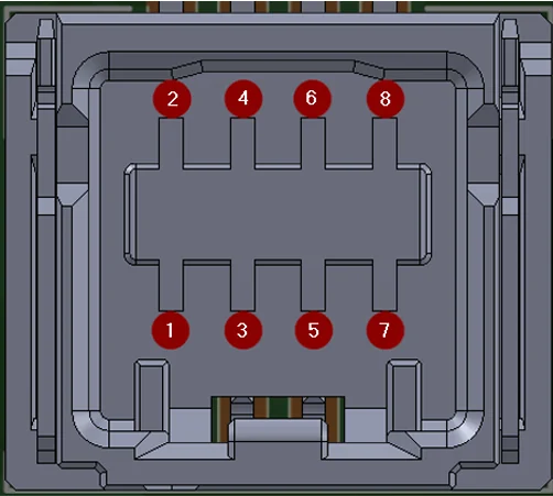
Connect the USB interface using the following pin assignments:- Connect USB D+ to pin 6 (USB-P).
- Connect USB D- to pin 8 (USB-N).
- Connect GND to both pin 4 and pin 5.
- Supply the full device power (up to 3 W peak) from the host via pin 7 (Vin Ext).
Enumeration
Upon USB connection, the UNO-mini enumerates as a CDC (Communications Device Class) virtual serial port. The host OS assigns a COM port on Windows or a/dev/ttyACMx device node on Linux and Android.
- Linux and Android: No custom USB driver is required.
- Windows: The standard CDC driver (
usbser.sys) is used. Install it manually if it is not loaded automatically.
Cable requirements
Observe the following requirements when designing or selecting the USB cable:-
USB D+ and D- lines must be a twisted pair with impedance of 90 Ω ±15 Ω.

- Maximum cable length: 3 m (per USB 2.0 specification for Full Speed devices).
- Use a shielded cable to minimize EMI. Connect the shield to chassis ground at the host end only (single-point grounding).
- Do not route the USB cable in the same conduit as high-current power wiring.
Hot-plugging the USB cable is not expected during normal operation. Ensure the host application handles USB disconnection and reconnection events gracefully and restores the communication session automatically.
UART TTL connection
The UNO-mini supports UART TTL communication as an alternative to USB.Signal lines
Connect the UART interface using the following pin assignments:- Connect UART TX from the UNO-mini (host RX) to pin 1 (Host UART RX).
- Connect UART RX to the UNO-mini (host TX) to pin 2 (Host UART TX).
- Supply power (Vin) on pin 7, and connect GND to pins 4 and 5.
UART parameters
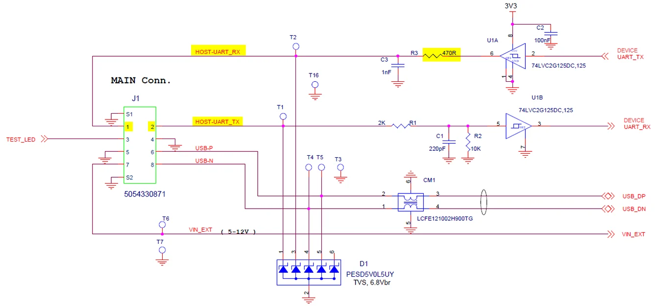
The following table lists the UART interface parameters.Host RX input impedance
The UNO-mini TX output line includes a 470 Ω series resistor as part of an RC filter. To avoid excessive voltage drop on the TX line, the host RX input impedance must meet the following requirements:- Minimum: 5 kΩ
- Recommended: 10 kΩ to 100 kΩ (ensures less than 10% voltage drop across the 470 Ω series resistor)
Cable recommendations
Follow these guidelines when routing UART wiring:- Maximum cable length: 1 m at 115,200 baud without additional line conditioning.
- Use shielded twisted pair for UART TX/RX lines. Reduce baud rate if communication errors occur.
- Keep UART wiring away from high-current power lines and switching power supplies to minimize noise coupling.
- In noisy environments, add ferrite beads at both ends of the UART lines.
Next steps
Get Started with EMV Core
Install the EMV Core SDK and begin your software integration.
EMV Core Integration Process
Review the integration and certification milestones for your EMV Core project.